Uživatelské nástroje
Obsah
This is not the final version
Project Goals
- Design hardware part of heating regulator to control three heating elements (2kW ~230V each)
- Design homebrewing control unit which will take care of:
- Temperature measuring
- Temperature PID regulation
- Stirring control
- Character display GUI controlled by buttons
- RTC
- Basic cooking program functionality
- Create own C drivers (display, RTC, …)
Regulator HW
Principle
Regulator acts as power switch driven by low-frequency PWM signal from MCU. For safety and lucidity purposes, regulator will be placed at separate PCB, its interface to MCU will consist of logic supply pins and single trigger pin for each driven phase.
Switching component
Power triac was chosen as sufficient switch component in terms of power/price efficiency. Any triac allowing >12A continual working current (incl. 3A margin) would be acceptable (BTA12-600B - TO220 ~0.8$), however these packages do not provide insulation to common terminal (case). This problem would require additional electric insulation between the package and the heatsink, in cost of worsening thermal insulation. In case of common heatsink to all 3 triacs (3 phases), the peak voltage will reach over 500V peak. This lead to use of BTA26B/600V - TOP3 ~3.6$ as one of the cheapest available triacs with insulated package.
Logic
Optotriac provides considerable solution for direct drive of power triac, together with ensuring galvanic isolation of power and logic part. MOC3031 is optotriac with builtin logic providing zero-cross switching, which decreases power loss on power triac and significantly reduces EMI.
Scheme

PCB

MCU
MSP430G2553 from TI was chosen as the MCU for this project. MSP430 family are 16-bit RISC microcontrollers aimed at simplicity and extremely low power consumption. MSP430G2553 (in PDIP-20) has 10 bit ADC unit, common interface peripherals (I2C, SPI, UART) and two 16-bit timers with 3 capture/compare units.
Temperature Control
Temperature Measurement
Currently tested temperature measuring is based on direct measure of output voltage of LM35 - precision centigrade temperature sensor from TI, packaged in TO92. Its output voltage gets increased by 10mV per 1°C rise. Sensor is loaded with 1k pulldown resistor and connected directly to ADC input.
If this package proves to be unsuitable for microbrewery needs, LM35 will be replaced with PT100 temperature sensor packaged in stainless steel capsule, which will lead to small changes in temperature calculations (temp. calculated by reading from table). Hardware is designed to be suitable for both methods.
ADC
ADC circuitry is clocked from SMCLK/8 with internal reference (1.5V). Noise is reduced by use of sample and hold at 2kHz. ADC is triggered from timer interrupt and its value is further filtered with exponetial window. Detailed information about ADC settings are obvious from ADC init procedure (vid. init.c)
inline void init_ADC()
  void __attribute__ ((interrupt(ADC10_VECTOR))) ADC_ISR (void)
  {
    temp_current = (ALPHA * ADC10MEM) + (1.0 - ALPHA) * temp_current;
  }
PID regulator
Proportional - Integral - Diferential (PID) regulator is used for driving of output unit (motors, heaters, …) based on input values (rpm, temperature). Output value consists of sum of P, I and D parts. Proportional contribution is difference of current value and required value, integral contribution is accumulator of all previous and current errors and differential contribution represents the difference (trend) of current and previous error at measured time. To ensure required functionality, all three contributions must be weighted by coefficients, depending on system. PID is implemented in getPID() function:
#define KP   24
#define KI   0.2
#define KD   60

uint8_t getPID(float set_point, float measured_value){
  float actual_error, P, D;
  static float error_previous;
  static float I;

  actual_error = set_point - measured_value;
  // PID
  P  = actual_error;   //Current error
  I += error_previous;  //Sum of previous errors
  D  = actual_error - error_previous;  //Difference with previous error

  error_previous = actual_error;

  float result = KP*P + KI*I + KD*D;

  if(result > 254)
    result = 255;

  if(result < 0)
    result = 0;

return result;
}
While the output of PID regulator is directly driving the 8bit PWM controller, output value must be limited to fit uint8_t borders.
Output control
Phase outputs will be driven by custom low frequency PWM signal. This PWM is needed to be done by hand, because hadware PWM can not run on low frequencies. In this project, each output (phase) has its own uint8 register (Phase Duty Counter PDC) which is being incremented in intervals given by Timer A CC0 unit (and is repeatedly overflowing).Those registers are representing progress within uint8 Global Duty Cycle register. At each CC0 interrupt, PDCs are compared with global duty cycle register and appropriate output pins are set or reset.
// TACC0
void __attribute__ ((interrupt(TIMER0_A0_VECTOR))) Timer_A_ISR (void)
{
  static uint8_t ptr1 = 0;
  static uint8_t ptr2 = HEATER_MARGIN;
  static uint8_t ptr3 = 2 * HEATER_MARGIN;

    // TACCR0 interval : 50Hz
    TACCR0 += 2500;

    if(ptr1 < g_duty)
      P1OUT |= BIT0;
    else
      P1OUT &= ~BIT0;

    if(ptr2 < g_duty)
      P1OUT |= BIT2;
    else
      P1OUT &= ~BIT2;

    if(ptr3 < g_duty) {
      P1OUT |= BIT3;
    }else{
      P1OUT &= ~BIT3;
    }

    ptr1++;
    ptr2++;
    ptr3++;
}
While PDCs are static variables affected only by periodical increments, those can be preset differently. If so, outputs are ensured not to be switched on or off at the same time all along the program runtime. If loads are powered from single phase, this will significantly reduce peak switching current (same principle as time relays) and thus EMI. The delay between triggering particular outputs is called Phase Margin and is obvious from figure below (margin 5ms):
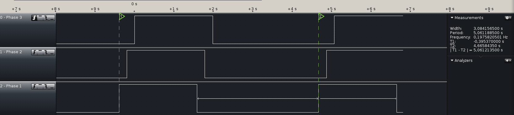
While counter period is 50Hz and counter length is 8b, PWM period is given by:
T = counter_period * counter_length = 20E-3 * 255 = 5,1s
Stir control
Stirring control will be switched by power switch driven directly from MCU by putting single pin to logical „1“ or „0“ by hand or at predefined time intervals. Vid. section „programming“.
Display interface
Character display module with 4×20 characters was chosen as display unit. This display module contains HD44780 display driver with 8b/4b paralel interface.
These functions are currently provided (hd44780.h):
void display_init();
void display_clear();
void display_return_home();
void display_goXY(uint8_t x, uint8_t y);
void display_print_char(const char character);
void display_print(const char *text);
void display_printxy(const char *text, uint8_t x, uint8_t y);
Menu
Menu strings are saved in string array. On display redraw, string adressed by global „menu index“ variable is shown. First button controls rolling over menu nodes (menu index), remaining two buttons control change of variable of interest (temperature, stir, program flow).
RTC
Embeded module with DS3231 RTC chip was used as RTC source. This module is connected via I2C interface to MCU, contains temperature-compensated crystal, battery and additional 32k EEPROM memory. This chip can also serve as time generator and can act as an alarm (raising pin at desired time), however none of these functions are used in this project. At this time, RTC chip will serve only as a clock source.
Setting and reading time is done simply by reading or writing appropriate register on RTC chip. Time values are stored in BCD, a small calculation is thus needed before writing or after reading to display the value.
DS3231 driver currently provides these functions (ds3231.h):
uint8_t rtc_get_seconds();
uint8_t rtc_set_seconds(uint8_t seconds);
uint8_t rtc_get_minutes();
uint8_t rtc_set_minutes(uint8_t minutes);
uint8_t rtc_get_hours();
uint8_t rtc_set_hours(uint8_t hours);
Timer
Single 16b timer clocked at 125kHz and 3 CC units are used as interval timers.
- CC0 (20ms) handles phase outputs (LFPWM).
- CC1 (100ms) handles redraw of the display (1s), calculation of the PID and ADC triggering (3s) and increments brewing program counter.
- CC2 (1,6ms) serves for buttons debounce
Conclusion
This project uses newlib, the c library for embedded systems. At first, sprintf() from previously mentioned library was used for string handling, however, this function at its own consumed over 5kB of program memory which is totally unacceptable and must be replaced by custom simplified implementation. For mitigation of program size, specialized custom string functions were implemented. Currently, not all goals are fullfilled because of program memory size. The use of Link Time Optimalization decreases the binary size to 14kB however for some reason LTO optimizes out interrupt service routines even if „used“ attribute is attached on them. The video shows current functionality including simple user menu. Desired temperature is set and PID is turned on. Whole project is assembled on breadbord, the temperature sensor is attached to power resistor, whose current is controlled by power transistor on phase 1 output. The temperature fluctuations are caused by current induced from power resistor current, these fluctuations are also causing increase of differential error of PID regulator and will be negligible on final hardware assembly. Further work on this project will consist of optimalization of i2c routines (use of interrupts) and float operations.
Full source available at: https://github.com/Degress/MSBrew/tree/master/src